
Gas Compression Engines:
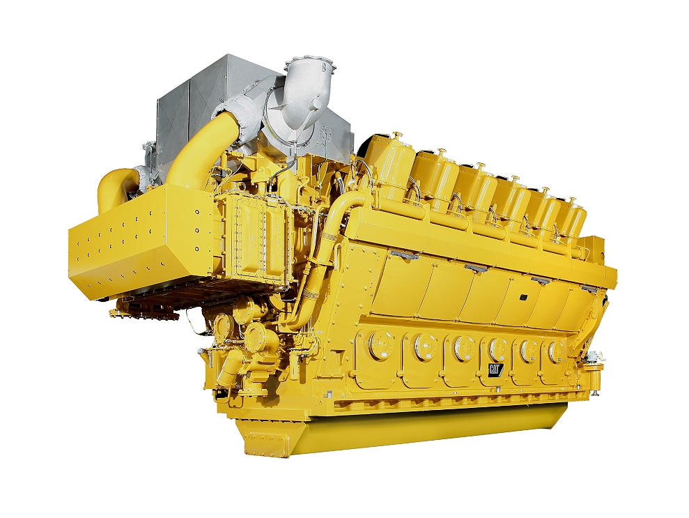
G12CM34 Gas Engine
Contact Us About This Product
Click a link to download the document:
- Minimum Rating
- 6135 HP
- Maximum Rating
- 6135 HP
- Emissions
- U.S. EPA SI NSPS Site Compliant Capable
- Displacement
- 10 kW/L (0.22 hp/in3
The G12CM34 is a natural gas, spark ignited, V-style, turbo charged and aftercooled engine that provides: low emissions, high efficiency, high reliability, high flexibility, constant torque and variable speed. The engine achieves high efficiency and low emissions by utilizing solenoid operated gas admission valves, enriched prechamber design, and Cat® ADEM A3 control technology.
Product Specs
-
Engine Specifications
- Minimum Rating
- 6135HP
- Maximum Rating
- 6135HP
- Emissions
- U.S. EPA SI NSPS Site Compliant Capable
-
Displacement
- Displacement
- 10 kW/L (0.22 hp/in3
-
Compression Ratio
- Compression Ratio
- 11.4:1
-
Aspiration
- Aspiration
- Turbocharged-2 Stage Aftercooled
-
Governor and Protection
- Governor and Protection
- Electronic (ADEM™ A3)
-
Rotation from Flywheel End
- Rotation from Flywheel End
- Counterclockwise
-
Flywheel Teeth
- Flywheel Teeth
- 408
-
Weight - Dry
- Weight - Dry
- 66000kg
-
Oil Change Interval
- Oil Change Interval
- 7500 hrs
-
Stroke
- Stroke
- 420mm
-
Bore
- Bore
- 340mm
Equipment
-
- Air Inlet System
-
- Turbocharger Inlet Adapter - provides a flexible connection between engine mounted turbocharger inlet and customer inlet air piping
- Air Filter Units - Two air filter housings for remote installation, one per turbocharger, are designed for normal environmental conditions. Each filter housing contains six (6) dry filter elements. A single filter housing with twelve (12) filter elements is offered as optional
- Air Intake Silencer – an in-line tubular air silencers designed for 30 dB(A) noise reduction
-
- Cooling System
-
- The engine includes an auxiliary skid that combines the cooling system and lubrication system functions. The standard cooling system separates the High Temperature (HT – includes JW) circuit from the Low Temperature (LT – includes 2nd stage of aftercooler) circuit. Thermostatic valves are included for each circuit. Two-stage charge air cooler splits heat load between the HT and LT circuit, reducing the heat load to the LT system, minimizing cooler costs. The lube oil system includes a automatic filter, plate and frame oil cooler, an engine-mounted gear-driven lubrication pump, and an electric motor-driven pre/post-lubricating pump. A pneumatically actuated thermostatic valve (controlled by the engine control panel) controls the lube oil temperature. All components mounted on a single baseplate with drip pan for pollution control. Interconnecting pipe between engine and cooling water/lube oil skid are by customer. Engine controls are by customer.
- Set of Flexible Connectors at the engine for cooling water piping
-
- Crankcase Ventilation Systems
-
- - Design includes multi-stage oil remover with metal elements and paper filter - Capacity – 340 m3/h (200 scfm)
-
- Cylinder Block
-
- - One-piece design for strength and rigidity - Underslung crankshaft reduces weight and provides easy access to bearings for service - Dry cylinder block (waterless) offers reduced repair times and increased strength - Crankcase pressure relief devices - Designed for block or skid mounting
-
- Cylinder Head
-
- - Individual cylinder heads with two inlet and two exhaust valves per cylinder - Water-cooled exhaust seats to increase life - Nitrided valves with automatic rotators
-
- Drive Coupling
-
- A torsionally elastic high damping steel spring coupling is provided. The TVA study with up to eight compressor load cases is included.
-
- Engine Controls And Instrumentation
-
- The engine utilizes the ADEM A3 engine management system for speed regulation, individual cylinder detonation control, closed loop air/fuel ratio control, engine monitoring and protection. Electronically controlled pneumatic actuated valves control the main and pilot fuel gas pressure. System also includes an operator interface for displaying operating parameters and system messages. This system includes a local control panel with PLC for additional engine management and protection. Protection provided by this system includes: - Engine control panel with PLC and operator control interface - Floor-standing enclosure with window kit for touch screen - Supplied local control panel includes space to incorporate compressor PLC, which can be displayed on same screen
-
- Exhaust Gas System
-
- Exhaust Bellows - provides a flexible connection at engine mounted turbocharger outlet only (additional bellows that may be required in the rest of exhaust gas piping system not included)
-
- Flywheels & Flywheel Housings
-
- A flywheel with starting ring gear is shipped mounted, cover/guard not included.
-
- Fuel System
-
- Gas Regulating Unit – independently controls the gas supply pressure to the main combustion chamber and pre-chamber. The skid is certified for Class 1, Division 2, Group D hazardous location.
- Set of Flexible Connectors at the engine for main chamber and pre-chamber piping
-
- Lube-oil System
-
- The lube-oil part of the auxiliary skid includes the following components:
- Crankcase Ventilation Unit – maintains negative pressure in the crankcase for safety. Includes cyclone filter that removes oil from the fumes.
- Set of Flexible Connectors at the engine for lube-oil piping
-
- Painting
-
- The engine is painted Cat yellow, other colors can be provided. Caterpillar Motoren's standard paint system will be used.
-
- Starting System
-
- Equipped with turbine-type air starters (TDI) uses compressed air or natural gas for engine starting; 1,034 kPa (150 psi) minimum air pressure. Rear mounted.
- Set of Flexible Connectors at the engine for start air/gas piping
- Barring Device Controller – handheld controller with hoses and oiler
-
- Testing
-
- Each engine is factory tested before shipment from Kiel, Germany. Test reports will be provided as part of the standard documentation.
-
- Control System
-
- Local Control Panel – PLC based system that control, monitor and display parameters of the engine and main engine auxiliaries. The panel is certified for Class 1, Division 2, Group D hazardous location.
-
- General
-
- Flexible Coupling – flexible coupling between engine and driven equipment (compressor)
- Barring Device Controller – handheld controller with hoses and oiler
- Torsional Vibration Analysis (TVA) of up to eight (8) load cases
-
- Air Inlet System
-
- Inlet air Pre-heater – required for inlet air temperature below -20°C (-4°F)
-
- Exhaust Gas System
-
- Exhaust Ventilation System – purge the entire exhaust gas system to maintain gas concentration below ignition point reducing the risk of exhaust gas explosion. The skid is certified for Class 1, Division 2, Group D hazardous location.
-
- General
-
- Bearing Temperature Monitor – to monitor temperature of the main crankshaft bearings and the connecting rod big end bearings. Engine Special Tools – set of special tools for GCM34 engines.